
|
|
 Rotor and stator gluing
Rotor and stator wire cutting
Stator powder coating
Double - sided punching of disc - type stator
Grinding the end face of disc - type stator
Stator stamping
Polygonal correction of disc - type stator
Stress relief annealing of rotor and stator
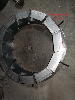
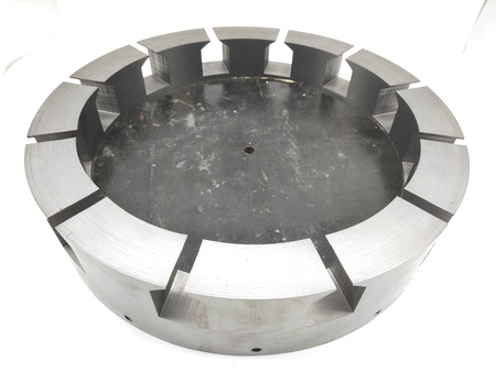
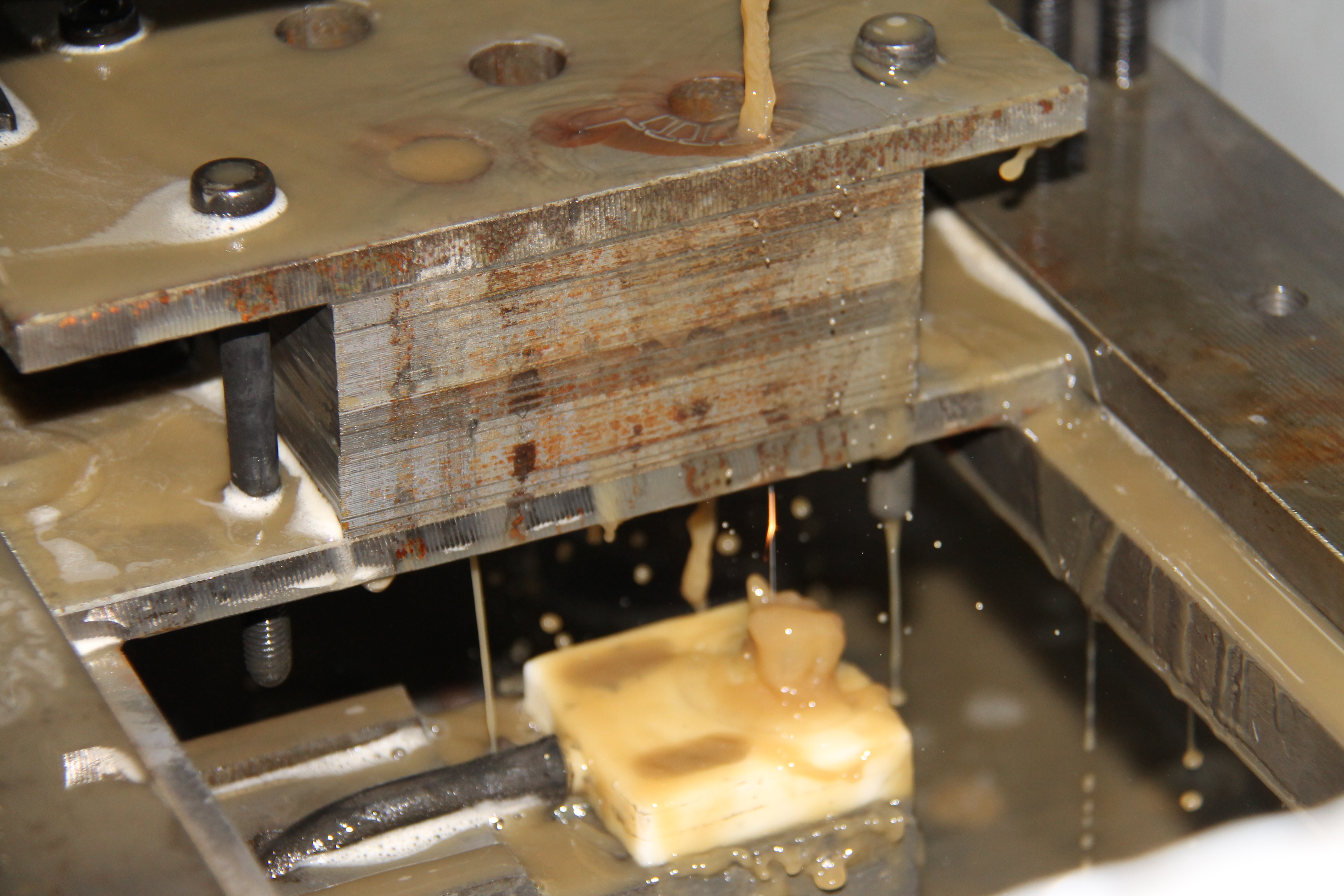 How to do a good job in wire cutting of silicon steel sheet stators and rotors? Wire cutting of silicon steel sheets is the optimal solution for customized core samples. Compared with laser cutting and other cutting processes, wire cutting has the following advantages: 1. It can achieve a tolerance dimension of within +/-0.02mm for the entire product, and can avoid the problem of uneven appearance caused by the dimensional difference fluctuations of single sheets in laser cutting. 2. Since there is always coolant for cooling during the wire cutting process, it can minimize the increase in iron loss caused by thermal stress and punching shear stress. Through relevant research and tests, among the four processing technologies of stamping, laser cutting, water jet cutting, and wire cutting, wire cutting has the smallest iron loss value. 3. The surface roughness of wire - cut products is significantly better than that of products cut by laser or stamped. 4. Since wire cutting is an electro - erosion process, there is theoretically almost no possibility of burrs, which is beneficial for improving the lamination factor of the product; and the lamination factor is closely related to the final performance of the motor. Best utilizes many years of experience in wire cutting of silicon steel sheets and has accumulated years of manufacturing and processing experience. It can provide customers with the optimal solutions in terms of product cost, performance, workability, and delivery time. 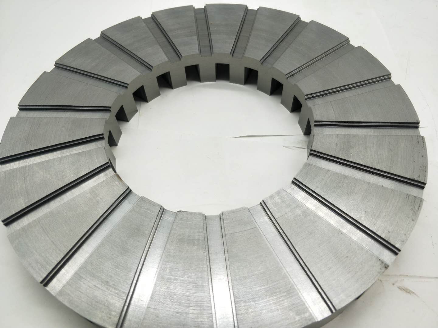 PressAccording to the general production process of the Axial fulx motor stator, stamping and winding are carried out integrally. Each time one tooth is punched, the servo system drives the coil stock to move. However, if there are teeth on two planes of the stator, how should it be handled? There are two situations: 1. The two teeth of the stator are in parallel positions: Only need to design another punch when designing the mold, and the two teeth can be stamped synchronously; 2. The two teeth of the stator are misaligned: Since the distance between the two teeth increases as the winding radius becomes larger, the traditional mold can no longer meet the requirements; a dynamic stamping die must be designed, that is, the punch is in a moving state, and the stamping time and cycle are precisely controlled by a computer to achieve the required stamping result; Best has been focusing on the production and process R & D of Axial fulx motor stators for many years, and has complete production and manufacturing experience for Axial fulx motor stators, including stamping, drilling, end - face grinding, annealing, and winding; 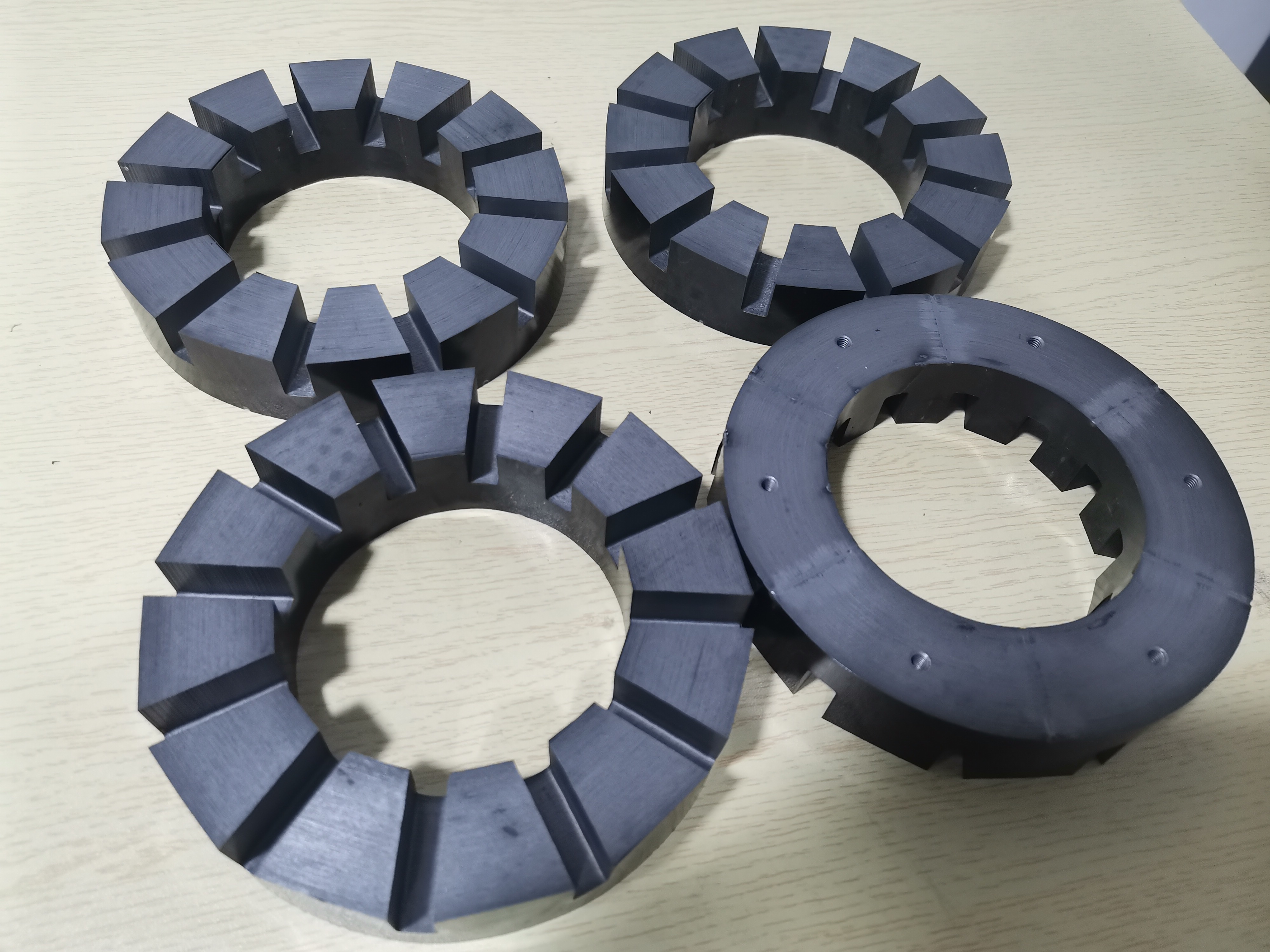 Generally speaking, except for wire cutting, which cools the product with coolant in real - time and thus has relatively small internal thermal stress, all other processing technologies, such as laser cutting and punch stamping, will generate a certain amount of stress on the sheared cross - section. This stress will disrupt the internal magnetic field distribution of the silicon steel sheet, resulting in an increase in losses. The thermal stress annealing process is a special treatment process carried out to improve the performance of the product after stamping. Axial flux stators are generally produced by special equipment through stamping and winding. Therefore, it is inevitable that a certain amount of punching and shearing stress will be generated at the stamping part during the stamping process, which increases the eddy current of the motor. Therefore, for high - performance axial flux stators, we recommend annealing heat treatment to eliminate the internal stress of the axial flux stator and improve its performance. Baist has many years of experience in the production of rotors, stators, and motors. It can perform targeted annealing treatment according to the material characteristics of different silicon steel sheets. 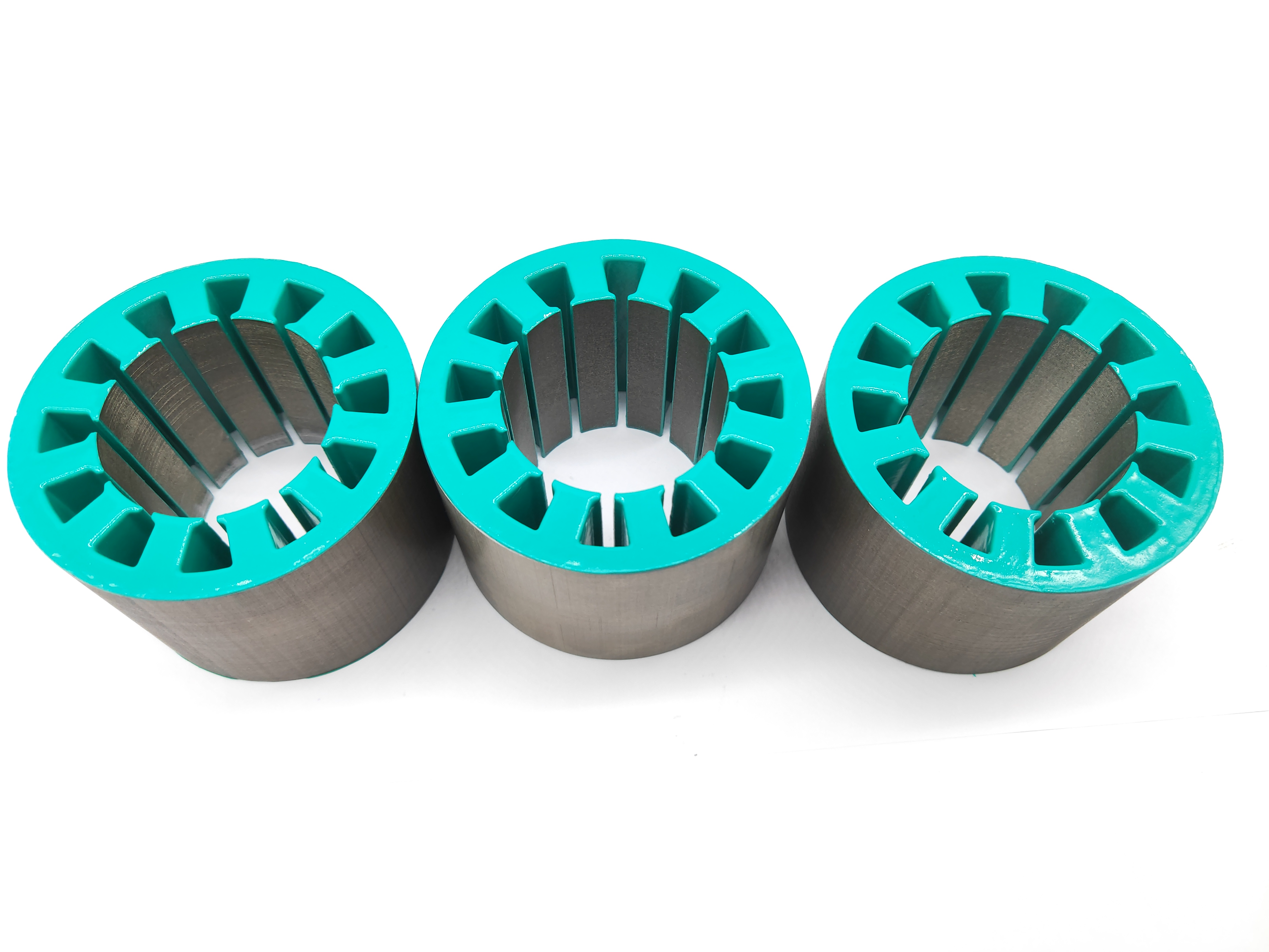 For general brushless DC motors and other motors, an insulating layer must be added between the enameled wire and the stator slot to prevent the formation of a conductive circuit and ensure the generation of an ideal magnetic field. Generally, there are three ways to insulate the slots: A. Injection molding: Use insulating plastics with high voltage resistance and form them through an injection mold. This is the most cost - effective solution for mass - producing stators, but the investment in mold costs is relatively high. Additionally, it is difficult to find materials with excellent insulating properties that can withstand temperatures above 220 degrees. B. Slot paper: This is the most common insulation method for high - voltage motors. Since it requires manual shaping or the use of expensive slot - paper insertion machinery, it is generally suitable for small - batch or ultra - high - voltage motors. C. Insulation coating: Since the coating thickness can be set by adjusting the temperature or the parameters of the coating machine, it can meet the coating requirements of products within a certain thickness range. Moreover, an electrostatic coating machine can achieve continuous production, with a daily output of about 10,000 pieces, which is sufficient to meet the needs of mass production. Insulation coating has the following features: 1. It can withstand a maximum temperature of 180 degrees (H - grade temperature resistance). Commonly used materials include 3M5555, 3M260, 3M860E, 3M5230N, etc. 2. The thickness can be adjusted within the range of 0.1 - 0.6mm. 3. It has a certain strength to enhance the lamination pressure of the iron core. 4. There are various colors of insulating powder available, making your stator products stand out in terms of color. 5. The insulation coating has a certain corrosion - resistance ability. 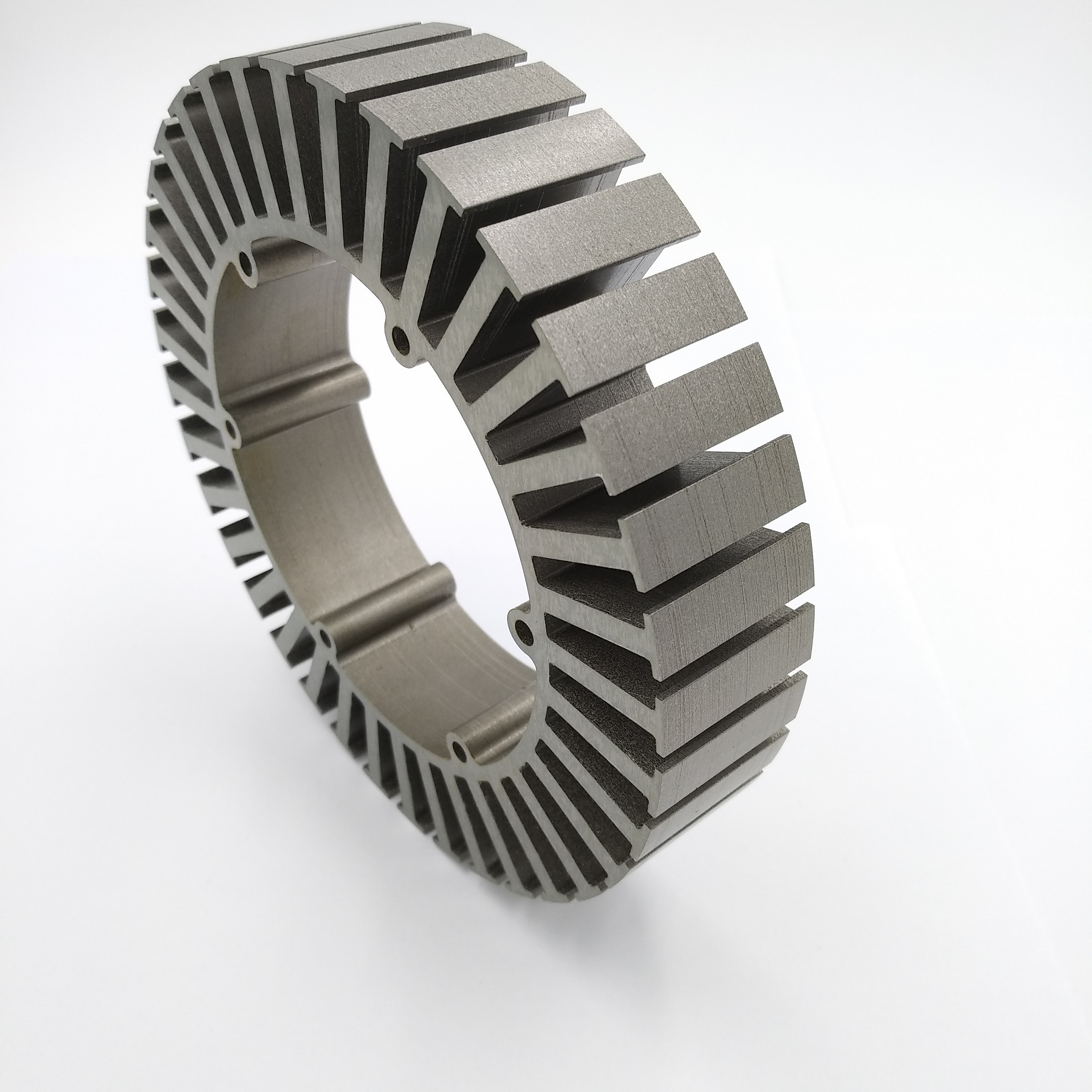 When designing a motor, the eddy current loss of the stator and rotor is an unavoidable problem. High - performance and high - speed motors are more sensitive to iron loss and motor efficiency. Therefore, how to reduce the iron loss has become a major consideration. Besides choosing thinner silicon steel sheets as the main design idea, how to avoid the eddy current loss caused by the conduction of inter - layer insulation of silicon steel sheets has become an important consideration. The adhesive technology for stator and rotor loose sheets has become the optimal solution because traditional riveting, self - fastening, and welding cannot fundamentally prevent the inter - layer conduction of silicon steel sheets. Baiste has developed an adhesive process suitable for iron - core stator products through years of technological research and development to meet the needs of mass production; Our technological advantages: 1. Through relevant tests, a lamination coefficient of 96 - 98% can be achieved (based on 0.2mm silicon steel sheets); 2. Imported glue with UL certification that can withstand a high temperature of 200 degrees is used to ensure the safety of its electrical performance. 3. In theory, any additional loss can be avoided. After adopting other suitable processes, it can be ensured that the iron loss of the entire iron - core product meets the relevant parameters in the material specification sheet (there are relevant test reports). 4. Since glue is used for fixing between layers, the noise of the motor at high speed has been significantly reduced compared with that using the welding process. 5. Since the relevant glue forms a protective film on the product surface, it has a certain improvement effect on the anti - rust oil of the product. 6. For a general new - energy vehicle stator product with an outer diameter of 200mm and a height of 150mm, our company has a daily production capacity of 100 sets of products, and the production capacity can be increased by 5 times within 1 month according to the order requirements. The production process of the Axial flux motor stator is stamping + winding. Through the control of a precision system, these two processes are carried out synchronously. The number of teeth and the lamination thickness are both determined by the settings of the operating system; In fact, when winding, since the tooth material of the Axial flux motor stator product has been stamped and sheared off, it cannot be wound in a theoretical circular shape, but will become a polygon. The side length of the polygon is directly related to the size of the stator and the number of teeth; When the outer diameter of the stator is relatively large (over 200mm) or the number of its teeth is less than 24, this polygon will be more obvious; Best can correct the polygon arc of the Axial flux motor stator through a unique technical solution, so that the outer diameters of all stators approach the theoretical arc shape; The following picture shows the difference in results when the stator is subjected to polygon correction and when it is not.
|
Contact: Mike Qi
Mobile phone: +86 13751018358
Email: sales@best-statorrotor.com
WhatsApp: +86 13751018358
Telephone:+86 0769 82608280
Contact: Angel
Email: angel@best-statorrotor.com
WhatsApp: +86 13367372478